 |
HP OpenVMS systems documentation |
| Previous | Contents | Index |
The stack of a stack frame procedure consists of a fixed part (the size of which is known at compile time) and an optional variable part. There are two basic types of stack frames:
Even though the exact contents of a stack frame are determined by the compiler, all stack frames have common characteristics.
Various combinations of PDSC$V_BASE_REG_IS_FP and PDSC$L_SIZE can be used as follows:
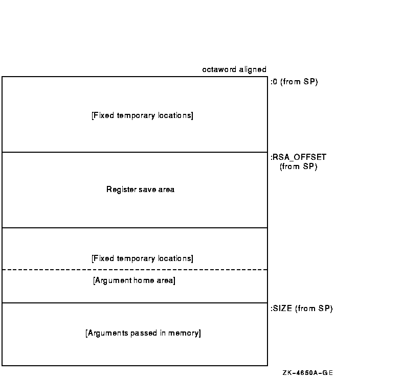
Figure 3-2 illustrates the format of the stack frame for a procedure with a fixed amount of stack that uses the SP register as the stack base pointer (when PDSC$V_BASE_REG_IS_FP is 0). In this case, R29 (FP) typically contains the address of the procedure descriptor for the current procedure (see Section 3.5.1).
Some parts of the stack frame are optional and occur only as required by the particular procedure. As shown in the figure, the field names within brackets are optional fields. Use of the arguments passed in memory field appending the end of the descriptor is described in Sections 3.4.3.3 and 3.7.2.
For information describing the fixed temporary locations and register save area, see Sections 3.4.3.3 and 3.4.3.4.
Figure 3-2 Fixed-Size Stack Frame Format

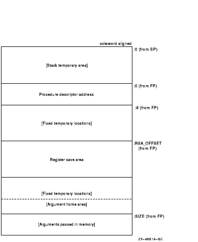
Figure 3-3 illustrates the format of the stack frame for procedures with a varying amount of stack when PDSC$V_BASE_REG_IS_FP is 1. In this case, R29 (FP) contains the address that points to the base of the stack frame on the stack. This frame-base quadword location contains the address of the current procedure's descriptor.
Figure 3-3 Variable-Size Stack Frame Format

Some parts of the stack frame are optional and occur only as required by the particular procedure. In Figure 3-3, field names within brackets are optional fields. Use of the arguments passed in memory field appending the end of the descriptor is described in Sections 3.4.3.3 and 3.7.2.
For more information describing the fixed temporary locations and register save area, see Sections 3.4.3.3 and 3.4.3.4.
A compiler can use the stack temporary area pointed to
by the SP base register for fixed local variables, such as
constant-sized data items and program state, as well as for dynamically
sized local variables. The stack temporary area may also be used for
dynamically sized items with a limited lifetime, for example, a
dynamically sized function result or string concatenation that cannot
be stored directly in a target variable. When a procedure uses this
area, the compiler must keep track of its base and reset SP to the base
to reclaim storage used by temporaries.
3.4.3.3 Fixed Temporary Locations for All Stack Frames
The fixed temporary locations are optional sections of any stack frame that contain language-specific locations required by the procedure context of some high-level languages. This may include, for example, register spill area, language-specific exception-handling context (such as language-dynamic exception-handling information), fixed temporaries, and so on.
The argument home area (if allocated by the compiler) can be found with the PDSC$L_SIZE offset in the last fixed temporary locations at the end of the stack frame. It is adjacent to the arguments passed in memory area to expedite the use of arguments passed (without copying). The argument home area is a region of memory used by the called procedure for the purpose of assembling in contiguous memory the arguments passed in registers, adjacent to the arguments passed in memory, so all arguments can be addressed as a contiguous array. This area can also be used to store arguments passed in registers if an address for such an argument must be generated. Generally, 6 * 8 bytes of stack storage is allocated for this purpose by the called procedure.
If a procedure needs to reference its arguments as a longword array or construct a structure that looks like an in-memory longword argument list, then it might allocate enough longwords in this area to hold all of the argument list and, optionally, an argument count. In that case, argument items passed in memory must be copied to this longword array.
The high-address end of the stack frame is defined by the value stored
in PDSC$L_SIZE plus the contents of SP or FP, as indicated by
PDSC$V_BASE_REG_IS_FP. The high-address end is used to determine the
value of SP for the predecessor procedure in the calling chain.
3.4.3.4 Register Save Area for All Stack Frames
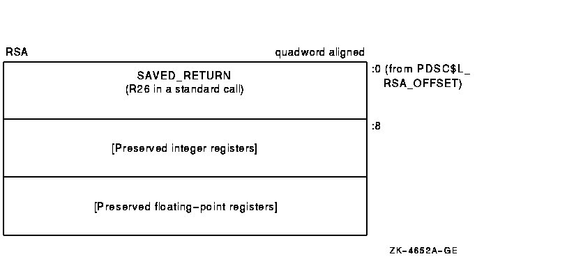
The register save area is a set of consecutive quadwords in which registers saved and restored by the current procedure are stored (see Figure 3-4). The register save area begins at the location pointed to by the offset PDSC$W_RSA_OFFSET from the frame base register (SP or FP as indicated by PDSC$V_BASE_REG_IS_FP), which must yield a quadword-aligned address. The set of registers saved in this area contain the return address followed by the registers specified in the procedure descriptor by PDSC$L_IREG_MASK and PDSC$L_FREG_MASK.
All registers saved in the register save area (other than the saved return address) must have the corresponding bit set in the appropriate procedure descriptor register save mask even if the register is not a member of the set of registers required to be saved across a standard call. Failure to do so will prevent the correct calculation of offsets within the save area.
Figure 3-4 illustrates the fields in the register save area (field names within brackets are optional fields). Quadword RSA$Q_SAVED_RETURN is the first field in the save area and it contains the contents of the return address register. The optional fields vary in size (8-byte increments) to preserve, as required, the contents of the integer and floating-point hardware registers used in the procedure.
Figure 3-4 Register Save Area (RSA) Layout

The algorithm for packing saved registers in the quadword-aligned register save area is:
Floating-point registers saved in the register save area are stored as a 64-bit exact image of the register (for example, no reordering of bits is done on the way to or from memory). Compilers must use an STT instruction to store the register regardless of floating-point type. |
The preserved register set must always include R29 (FP), because it will always be used.
If the return address register is not to be preserved (as is the case for a standard call), then it must be stored at offset 0 in the register save area and the corresponding bit in the register save mask must not be set.
However, if a nonstandard call is made that requires the return address register to be saved and restored, then it must be stored in both the location at offset 0 in the register save area and at the appropriate location within the variable part of the save area. In addition, the appropriate bit of PDSC$L_IREG_MASK must be set to 1.
The example register save area shown in Figure 3-5 illustrates the register packing when registers R10, R11, R15, FP, F2, and F3 are being saved for a procedure called with a standard call.
Figure 3-5 Register Save Area (RSA) Example

A register frame procedure does not maintain a call frame on the stack and must, therefore, save its caller's context in registers. This type of procedure is sometimes referred to as a lightweight procedure, referring to the expedient way of saving the call context.
Such a procedure cannot save and restore nonscratch registers. Because a procedure without a stack frame must use scratch registers to maintain the caller's context, such a procedure cannot make a standard call to any other procedure.
A procedure with a register frame can have an exception handler and can handle exceptions in the normal way. Such a procedure can also allocate local stack storage in the normal way, although it might not necessarily do so.
Lightweight procedures have more freedom than might be apparent. By using appropriate agreements with callers of the lightweight procedure, with procedures that the lightweight procedure calls, and by the use of unwind handlers, a lightweight procedure can modify nonscratch registers and can call other procedures. Such agreements may be by convention (as in the case of language-support routines in the RTL) or by interprocedural analysis. However, calls employing such agreements are not standard calls and might not be fully supported by a debugger; for example, the debugger might not be able to find the contents of the preserved registers. Because such agreements must be permanent (for upwards compatibility of object code), lightweight procedures should, in general, follow the normal restrictions. |
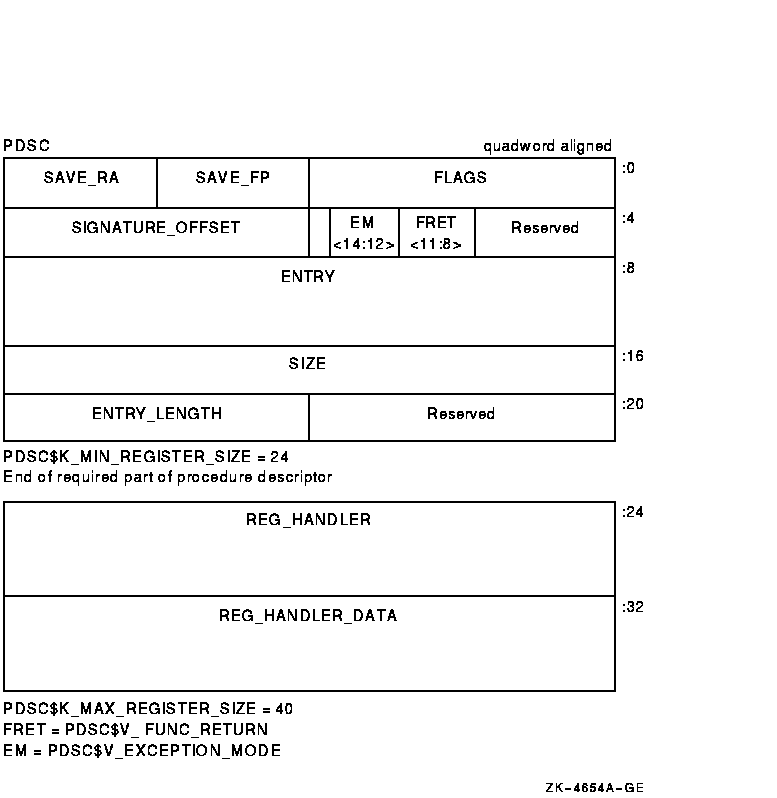
A register frame procedure descriptor built by a compiler provides information about a procedure with a register frame. The minimum size of the descriptor is 24 bytes (defined by PDSC$K_MIN_REGISTER_SIZE). An optional PDSC extension in 8-byte increments supports exception-handling requirements.
The fields defined in the register frame procedure descriptor are illustrated in Figure 3-6 and described in Table 3-4.
Figure 3-6 Register Frame Procedure Descriptor (PDSC)

| Field Name | Contents | ||||||||||||||||||
|---|---|---|---|---|---|---|---|---|---|---|---|---|---|---|---|---|---|---|---|
| PDSC$W_FLAGS |
The PDSC descriptor flag bits <15:0> are defined as follows:
|
||||||||||||||||||
||
|
|||||||||||||||||||
| PDSC$B_SAVE_FP |
Specifies the number of the register that contains the saved value of
the frame pointer (FP) register.
In a standard procedure, this field must specify a scratch register so as not to violate the rules for procedure entry code as specified in Section 3.6.5. |
||||||||||||||||||
| PDSC$B_SAVE_RA |
Specifies the number of the register that contains the return address.
If this procedure uses standard call conventions and does not modify
R26, then this field can specify R26.
In a standard procedure, this field must specify a scratch register so as not to violate the rules for procedure entry code as specified in Section 3.6.5. |
||||||||||||||||||
| PDSC$V_FUNC_RETURN |
A 4-bit field <11:8> that describes which registers are used for
the function value return (if there is one) and what format is used for
those registers.
Table 5-4 lists and describes the possible encoded values of PDSC$V_FUNC_RETURN. |
||||||||||||||||||
| PDSC$V_EXCEPTION_MODE |
A 3-bit field <14:12> that encodes the caller's desired
exception-reporting behavior when calling certain mathematically
oriented library routines. These routines generally search up the call
stack to find the desired exception behavior whenever an error is
detected. This search is performed independent of the setting of the
Alpha FPCR. The possible values for this field are defined as follows:
|
||||||||||||||||||
| PDSC$W_SIGNATURE_OFFSET | A 16-bit signed byte offset from the start of the procedure descriptor. This offset designates the start of the procedure signature block (if any). A 0 in this field indicates no signature information is present. Note that in a bound procedure descriptor (as described in Section 3.6.4), signature information might be present in the related procedure descriptor. A 1 in this field indicates a standard default signature. An offset value of 1 is not otherwise a valid offset because both procedure descriptors and signature blocks must be quadword aligned. | ||||||||||||||||||
| PDSC$Q_ENTRY | Absolute address of the first instruction of the entry code sequence for the procedure. | ||||||||||||||||||
| PDSC$L_SIZE | Unsigned size in bytes of the fixed portion of the stack frame for this procedure. The size must be a multiple of 16 bytes to maintain the minimum stack alignment required by the Alpha hardware architecture and stack alignment during a call (defined in Section 3.6.1). | ||||||||||||||||||
| PDSC$W_ENTRY_LENGTH | Unsigned offset in bytes from the entry point to the first instruction in the procedure code segment following the procedure prologue (that is, following the instruction that updates FP to establish this procedure as the current procedure). | ||||||||||||||||||
| PDSC$Q_REG_HANDLER |
Absolute address to the procedure descriptor for a run-time static
exception-handling procedure. This part of the procedure descriptor is
optional. It
must be supplied if either PDSC$V_HANDLER_VALID is 1 or
PDSC$V_HANDLER_DATA_VALID is 1 (which requires that
PDSC$V_HANDLER_VALID be 1).
If PDSC$V_HANDLER_VALID is 0, then the contents or existence of PDSC$Q_REG_HANDLER is unpredictable. |
||||||||||||||||||
| PDSC$Q_REG_HANDLER_DATA |
Data (quadword) for the exception handler. This is an optional quadword
and needs to be supplied only if PDSC$V_HANDLER_DATA_VALID is 1.
If PDSC$V_HANDLER_DATA_VALID is 0, then the contents or existence of PDSC$Q_REG_HANDLER_DATA is unpredictable. |
A procedure may conform to this standard even if it does not establish its own context if, in all circumstances, invocations of that procedure do not need to be visible or debuggable. This is termed executing in the context of the caller and is similar in concept to a conventional VAX JSB procedure. For the purposes of stack tracing or unwinding, such a procedure is never considered to be current.
For example, if a procedure does not establish an exception handler or does not save and restore registers, and does not extend the stack, then that procedure might not need to establish a context. Likewise, if that procedure does extend the stack, it still might not need to establish a context if the immediate caller either cannot be the target of an unwind or is prepared to reset the stack if it is the target of an unwind.
The circumstances under which procedures can run in the context of the caller are complex and are not fully specified by this standard.
As with the other procedure types previously described, the choice of whether to establish a context belongs to the called procedure. By defining a null procedure descriptor format, the same invocation code sequence can be used by the caller for all procedure types.
| Previous | Next | Contents | Index |